Friday, October 25, 2013

‘The Search’ is not yet over!

Published in Telecom Asia, Oc9, 2013 - 'The search' is not yet over!
In this post I take a look at the technologies that power the now indispensable and ubiquitous ‘search’ that we do over the web. It would be  easy to rewind the world by at least 3 decades by simply removing ‘the search’ from our lives.
A classic article in the New York Times, ‘The Twitter trap’ discusses how technology is slowly replacing some of our more common faculties like the ability to memorize or perform simple calculations mentally.
For e.g. until the 15th century people had to remember a lot of information. Then came Gutenberg with his landmark invention, the printing press, which did away with the need to store information. Closer to the 2oth century the ‘Google Search’ now obviates the need to remember facts about anything. Detailed information is just a mouse click away.
Here’s a closer look at evolution of search technologies
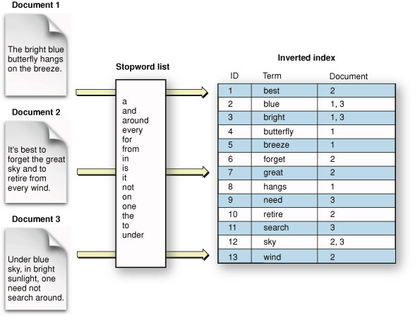
The Inverted Index: The inverted index is a way to search the existence of key words or phrases in documents.  The inverted index is an index data structure storing a mapping from content, such as words or numbers, to its locations in a document or a set of documents. The ability to store words and the documents in which it is present, allows for an quick  retrieval of the related documents in which the word(s) are present. Search engines like Google, Bing or Yahoo typically crawl of the web continuously and keep updating this index of words versus the documents as new web pages and web sites are added. The inverted index is a simplistic method and is neither accurate nor efficient.
inverted_index
Google’s Page Rank: As mentioned before merely the presence of words in documents alone is not sufficient to return good search results. So Google came along with its PageRank algorithm. PageRank is an algorithm used by the Google’s  web search engine to rank websites in their search engine results.  According to Google PageRank works by “counting the number and quality of links to a page to determine a rough estimate of how important the website is.”  The underlying assumption is that more important websites are likely to receive more links from other websites.
In essence the PageRank algorithm tries to determine the likelihood that a surfer will land on a particular page by randomly clicking on links. Clearly the PageRank algorithm has been very effective for searches as now ‘googling’ is synonymous to searching (see below from Wikipedia)
PageRanks
Graph database: While the ‘Google Search’ is extremely powerful it would make more sense if the search could be precisely tailored to what the user is trying to search. A typical Google search throws up a few 100 million results.  This has led to even more powerful techniques, one of which is the ‘Graph database’. In a Graph database data is represented as a graph. Nodes in the graph can be entities and edges could be relationships. A search on the graph database will result in the traversal of the graph from a specific start node to specific terminating node. Here is a fun representation of a simple Graph database representation from InfoQ
neo4j_matrix_0411
Google has recently come out with its Knowledge Graph which is based on this technology. Facebook allows users to create complex queries of status updates using the graph database.
Finally, what next??
A Cognitive Search??: Even with the graph database the results cannot be very context specific. What I would hope to happen in the future is have a sort of a ‘Cognitive Search’ where the results would be bounded and would take into account the semantics and context of a user specified phrase or request.
So for e.g. if a user specified ‘Events leading to the Iraq war’ the search should throw all results which finally culminated in the Iraq war.
Alternatively if I was interested in knowing for e.g. ‘the impact of iPad on computing’ then the search should throw precise results from  the making of the iPad, the launch of iPad, the various positive and negative reviews and impact iPad has had on the tablet and computing industry as a whole.
Another interesting query would ‘The events that led to the downfall of a particular government in election of 1998’ the search should precisely output all those events that were significant during this specific period.
I would assume that the results themselves would come out as a graph with nodes and edges specifying which event(s) triggered which other event(s) with varying degrees of importance.
However this kind of ability where the search is cognitive is probably several years away!
Find me on Google+

Future calls. Visualizing an IMS based future.

Future calls. In case you didn’t notice there is a word play in the previous sentence. I have used the word “calls” both as a verb and as a noun. Clever, right? ;-)

This post takes a closer look at how the future would look like with regard to calls.

Our world is getting more interconnected and more digitized. We view this digitized world through either smartphones, tablets, laptops, smart TV etc. So these days we can browse the web through any of the above devices. Social applications like Facebook. Twitter, LinkedIn or utilities like Evernote and Pocket are equally accessible through any of the devices at any time and at any place.

While we are able to use these devices interchangeably why is that we always receive calls only through phones (mobile or landlines).  Would it be possible to switch calls between these devices?

In fact this is very possible and is included in the vision that IP Multimedia Systems had set for itself. While IMS is yet to take off, it is bound to get traction in the not too distant future.

Assuming that this is going to happen, here is my visualization of how a typical day in the future (possibly 2015/2016) would look like.

Future calls

Here is an imagined scenario

Akash is joined to a conference call at 8.00 am, while at home. When he answers his smartphone he gets a notification “Nearby devices 1) Laptop2) Tablet 3) TV. Choose device to handover to”.  If he chooses the tablet, laptop or TV the call would be seamlessly transferred to this device.  When the call appears on his tablet, laptop or TV there could be another notification “Do you want to add video to the call? Choose Yes or No” the call would automatically be upgraded to a video call if the far end also has this capability. Lets assume that Akash completes this call.

On his way to the office he receives another call on his mobile. When Akash answers his smartphone he is again notified regarding the devices nearby 1) Laptop 2) Car dashboard. Now Akash can just command his smartphone to receive the call on his car dashboard if he is driving his car. If he is being driven he can handover the call to his laptop. When he receives the call in his laptop he could receive a popup, “Do you want to add video and/or data to this call?” If he chooses to add both video and data he can videoconference while also whiteboarding with his colleagues.

He can then continue the call on his smartphone while walking to his cubicle.

The transition between devices will be seamless.

This handover of calls between devices and also the switching back and forth from voice only to voice, video and data (whiteboarding) is bound to happen in the not too distant future.

So keep you ears and eyes wide open.
Find me on Google+

Envisioning a Software Defined IP Multimedia System (SD-IMS)

pot

In my earlier post “Architecting a cloud based IP Multimedia System (IMS)” I had suggested the idea of “cloudifying” the network elements of the IP Multimedia Systems. This would bring multiple benefits to the Service Providers as it would enable quicker deployment of the network elements of the IMS framework, faster ROI and reduction in CAPEX. Besides, the CSPs can take advantage of the elasticity and utility style pricing of the cloud.

This post takes this idea a logical step forward and proposes a Software Defined IP Multimedia System (SD-IMS).

In today’s world of scorching technological pace, static configurations for IT infrastructure, network bandwidth and QOS, and fixed storage volumes will no longer be sufficient.

We are in the age of being able to define requirements dynamically through software. This is the new paradigm in today’s world. Hence we have Software Defined Compute, Software Defined Network, Software Defined Storage and also Software Defined Radio.

This post will demonstrate the need for architecting an IP Multimedia System that uses all the above methodologies to further enable CSPs & Operators to get better returns faster without the headaches of earlier static networks.

IP Multimedia Systems (IMS) is the architectural framework proposed by 3GPP body to establish and maintain multimedia sessions using an all IP network. IMS is a grand vision that is access network agnostic, uses an all IP backbone to begin, manage and release multimedia sessions.

The problem:

Any core network has the problem of dimensioning the various network elements. There is always a fear of either under dimensioning the network and causing failed calls or in over dimensioning resulting in wasted excess capacity.

The IMS was created to handle voice, data and video calls. In addition in the IMS, the SIP User Endpoints can negotiate the media parameters and either move up from voice to video or down from video to voice by adding different encoders.  This requires that the key parameters of the pipe be changed dynamically to handle different QOS, bandwidth requirements dynamically.

The solution

The approach suggested in this post to have a Software Defined IP Multimedia System (SD-IMS) as follows.

In other words the compute instances, network, storage and the frequency need to be managed through software based on the demand.

Software Defined Compute (SDC): The traffic in a Core network can be seasonal, bursty and bandwidth intensive. To be able to handle this changing demands it is necessary that the CSCF instances (P-CSCF, S-CSCF,I-CSCF etc) all scale up or down. This can be done through Software Defined Compute or the process of auto scaling the CSCF instances. The CSCF compute instances will be created or destroyed depending on the traffic traversing the switch.

Software Defined Network (SDN): The IMS envisages the ability to transport voice, data and video besides allowing for media sessions to be negotiated by the SIP user endpoints. Software Defined Networks (SDNs) allow the network resources (routers, switches, hubs) to be virtualized.

SDNs can be made to dynamically route traffic flows based on decisions in real time. The flow of data packets through the network can be controlled in a programmatic manner through the Flow controller using the Openflow protocol. This is very well suited to the IMS architecture. Hence the SDN can allocate flows based on bandwidth, QoS and type of traffic (voice, data or video).

Software Defined Storage (SDS): A key component in the Core Network is the need to be able charge customers. Call Detail Records (CDRs) are generated at various points of the call which are then aggregated and sent to the bill center to generate the customer bill.

Software Defined (SDS) abstracts storage resources and enables pooling, replication, and on-demand provisioning of storage resources. The ability to be able to pool storage resources and allocate based on need is extremely important for the large amounts of data that is generated in Core Networks

Software Defined Radio (SDR): This is another aspect that all Core Networks must adhere to. The advent of mobile broadband has resulted in a mobile data explosion portending a possible spectrum crunch. In order to use the available spectrum efficiently and avoid the spectrum exhaustion Software Define Radio (SDR) has been proposed. SDRs allows the radio stations to hop frequencies enabling the radio stations to use a frequency where this less contention (see We need to think differently about spectrum allocation … now).In the future LTE-Advanced or LTE with CS fallback will have to be designed with SDRs in place.

Conclusion:

A Software Defined IMS makes eminent sense in the light of characteristics of a core network architecture.  Besides ‘cloudifying’ the network elements, the ability to programmatically control the CSCFs, network resources, storage and frequency, will be critical for the IMS. This is a novel idea but well worth a thought!
Find me on Google+

A closer look at “Robot Horse on a Trot” in Android

DSC00078This post is result of my dissatisfaction with the awkward and contrived gait of my Robot Walker in my earlier post "Simulating a Robot Walker” in Android. The movements seemed to be a little too contrived for my comfort so I decided to make a robot which has far more natural movements.

To do this I pondered on what constitutes a walking motion for any living thing. With a little effort it is clear that the following movements occur during walking

Mechanics of leg movements during walking

  1. The upper part of the leg swings upward and downward pivoted at the hip.

  2. The lower part of the leg, pivoted at the knee, swings in the opposite direction to the upper part of the leg. i.e when the upper part swings upward and counter-clockwise, the lower part of the leg swings downward & clockwise which results in the bend at the knees

  3. When one leg goes up, counterclockwise, the other leg goes down or it swing clockwise and vice versa. See figure below


  4. horse

    So with these rules it was easy to make the legs.

    Frontal leg (first leg)

    The upper part of the leg is connected to the Robot Body through a revoluteJoint with a pivot at the body. The upper leg has a motor and swings between an upper and lower limit

    // Create upper leg
    upperLeg = new Sprite(x, y, this.mLegTextureRegion, this.getVertexBufferObjectManager());

    upperLegBody = PhysicsFactory.createBoxBody(this.mPhysicsWorld, upperLeg, BodyType.DynamicBody, LEG_FIXTURE_DEF);

    this.mPhysicsWorld.registerPhysicsConnector(new PhysicsConnector(upperLeg, upperLegBody, true, true));

    this.mScene.attachChild(upperLeg);

    //Create an anchor/pivot at the body of the robot

    Vector2 anchor1 = new Vector2(x/PIXEL_TO_METER_RATIO_DEFAULT,y/PIXEL_TO_METER_RATIO_DEFAULT);

    //Attach upper leg to the body using a revolute joint with a motor

    final RevoluteJointDef rJointDef = new RevoluteJointDef();

    rJointDef.initialize(upperLegBody, robotBody, anchor1);

    rJointDef.enableMotor = true;

    rJointDef.enableLimit = true;

    rJoint = (RevoluteJoint) this.mPhysicsWorld.createJoint(rJointDef);

    rJoint.setMotorSpeed(4);

    rJoint.setMaxMotorTorque(15);

    //Set upper and lower limits for the swing of the leg

    rJoint.setLimits((float)(0 * (Math.PI)/180), (float)(30 * (Math.PI)/180));

    //Fire a periodic timer

    new IntervalTimer(secs,rJoint);

    The lower leg pivoted to the bottom of the upper leg through a revoluteJoint swings in the opposite direction of the upper leg between the reverse angle limts. By the way, I had tried every possible joint between the lower & the upper leg (distanceJoint, weldJoint,prismaticJoint) but the revoluteJoint is clearly the best.

    // Create lower leg

    lowerLeg= new Sprite(x, (y+50), this.mLegTextureRegion, this.getVertexBufferObjectManager());

    lowerLegBody = PhysicsFactory.createBoxBody(this.mPhysicsWorld, lowerLeg, BodyType.DynamicBody, LEG_FIXTURE_DEF);

    this.mPhysicsWorld.registerPhysicsConnector(new PhysicsConnector(lowerLeg, lowerLegBody, true, true));

    this.mScene.attachChild(lowerLeg);

    Vector2 anchor2 = new Vector2(x/PIXEL_TO_METER_RATIO_DEFAULT, (y+50)/PIXEL_TO_METER_RATIO_DEFAULT);

    //Create a revoluteJoint between upper & lower leg

    final RevoluteJointDef rJointDef1 = new RevoluteJointDef();

    rJointDef1.initialize(lowerLegBody, upperLegBody, anchor2);

    // The lower leg swings in opposite direction to upper leg

    rJointDef1.enableMotor = true;

    rJointDef1.enableLimit = true;

    rJoint1 = (RevoluteJoint) this.mPhysicsWorld.createJoint(rJointDef1);

    rJoint1.setMotorSpeed(-4);

    rJoint.setMaxMotorTorque(15);

    //Set upper and lower limits for the swing of the leg

    // Set appropriate limits for lower leg

    rJoint1.setLimits((float)(-30 * (Math.PI)/180), (float)(0 * (Math.PI)/180));

    new IntervalTimer(secs,rJoint1);

    Rear Leg (alternate leg)

    Every alternate leg moves in the converse direction as the previous leg

    //Create the alternative leg

    publicvoid createAltLeg(float x, float y, int secs ){

    // Create upper part of leg

    upperLeg = new Sprite(x, y, this.mLegTextureRegion, this.getVertexBufferObjectManager());

    upperLegBody = PhysicsFactory.createBoxBody(this.mPhysicsWorld, upperLeg, BodyType.DynamicBody, LEG_FIXTURE_DEF);

    this.mPhysicsWorld.registerPhysicsConnector(new PhysicsConnector(upperLeg, upperLegBody, true, true));

    this.mScene.attachChild(upperLeg);

    //Create an anchor/pivot at the body of the robot

    Vector2 anchor1 = new Vector2(x/PIXEL_TO_METER_RATIO_DEFAULT,y/PIXEL_TO_METER_RATIO_DEFAULT);

    //Attach upper leg to the body using a revolute joint with a motor

    final RevoluteJointDef rJointDef = new RevoluteJointDef();

    rJointDef.initialize(upperLegBody, robotBody, anchor1);

    rJointDef.enableMotor = true;

    rJointDef.enableLimit = true;

    rJoint = (RevoluteJoint) this.mPhysicsWorld.createJoint(rJointDef);

    // This leg swings in the opposite direction of the previous leg

    rJoint.setMotorSpeed(-4);

    rJoint.setMaxMotorTorque(15);

    //Set upper and lower limits for the swing of the leg

    rJoint.setLimits((float)(0 * (Math.PI)/180), (float)(30 * (Math.PI)/180));

    new IntervalTimer(secs,rJoint);

    // Create lower leg

    lowerLeg= new Sprite(x, (y+50), this.mLegTextureRegion, this.getVertexBufferObjectManager());

    lowerLegBody = PhysicsFactory.createBoxBody(this.mPhysicsWorld, lowerLeg, BodyType.DynamicBody, LEG_FIXTURE_DEF);

    this.mPhysicsWorld.registerPhysicsConnector(new PhysicsConnector(lowerLeg, lowerLegBody, true, true));

    this.mScene.attachChild(lowerLeg);

    Vector2 anchor2 = new Vector2(x/PIXEL_TO_METER_RATIO_DEFAULT, (y+50)/PIXEL_TO_METER_RATIO_DEFAULT);

    //Create a revoluteJoint between upper & lower leg

    final RevoluteJointDef rJointDef1 = new RevoluteJointDef();

    rJointDef1.initialize(lowerLegBody, upperLegBody, anchor2);

    rJointDef1.enableMotor = true;

    rJointDef1.enableLimit = true;

    rJoint1 = (RevoluteJoint) this.mPhysicsWorld.createJoint(rJointDef1);

    //The lower part of the leg has the opposite swing to the upper part

    rJoint1.setMotorSpeed(4);

    rJoint.setMaxMotorTorque(15);

    //Set appropriate upper and lower limits for the swing of the leg

    rJoint1.setLimits((float)(-30 * (Math.PI)/180), (float)(0 * (Math.PI)/180));

    // Fire a periodic timer

    new IntervalTimer(secs,rJoint1);

    I attached a horse's head to the body using a WeldJoint

    //Create the horse and attach the head using a Weld Joint

    horse = new Sprite(140, 320, this.mHorseTextureRegion, this.getVertexBufferObjectManager());

    horseBody = PhysicsFactory.createBoxBody(this.mPhysicsWorld, horse, BodyType.DynamicBody, HORSE_FIXTURE_DEF);

    this.mPhysicsWorld.registerPhysicsConnector(new PhysicsConnector(horse, horseBody, true, true));

    this.mScene.attachChild(horse);

    Vector2 anchor = new Vector2(140/PIXEL_TO_METER_RATIO_DEFAULT, 320/PIXEL_TO_METER_RATIO_DEFAULT);

    final WeldJointDef weldJointDef = new WeldJointDef();

    weldJointDef.initialize(horseBody, robotBody, anchor);

    this.mPhysicsWorld.createJoint(weldJointDef);

    So now I had a horse that was ready to trot or canter around.

    You can see the clip at Robot Horse on a canter using Android

    The complete code can be cloned at GitHub RobotHorse

    Some issues

    Here are some issues with the above code

    • The horse is quite unstable. If I move the phone vertically, the horse tends to tip backwards. The above clip was recorded with the phone lying on a table

    • The motor speeds, torque and the masses of the different objects have to be adjusted very carefully. If the horse's head or the body is too heavy the legs buckle under the weight

    • Sometimes when I start the simulation the horse seems to bounce off the floor


    • I have carefully adjusted the mass, friction, motor speeds etc very carefully. Feel free to play around with them.

      Comments & suggestions are welcome.
      Find me on Google+

      “Is it an animal? Is it an insect?” in Android

      walker“Is it an animal? Is it an insect?”. The answer is neither. In fact it is my version of a 'robot walker' in android using Box2D & AndEngine. I got interested in this simulation after I saw the Theo Jansen walker in JBox2D (look under Joints) . I did take a look at the code for this but I found it difficult to follow so I made my own version of a robot walker.

      In this connection I would like to point yot to an excellent and a fascinating TED talk by the creator Theo Jansen himself on “My creations, a new form of life”. His creations are really jaw- dropping.

      Anyway getting back to my post I thought about what would make the insect walk? After some thought I realized that I had to create a swinging motion of the upper part of the leg combined with the lower leg motion which does not bend that much.

      So I created a robot body which is a flat rectangular shape
      //Create the robot body

      robot = new Sprite(100, 360, this.mRobotTextureRegion, this.getVertexBufferObjectManager());

      robotBody = PhysicsFactory.createBoxBody(this.mPhysicsWorld, robot, BodyType.DynamicBody, BODY_FIXTURE_DEF);

      this.mPhysicsWorld.registerPhysicsConnector(new PhysicsConnector(robot, robotBody, true, true));

      this.mScene.attachChild(robot);

      Creating legs

      Then I create 6 different legs spaced apart

      createLeg(100,360,1);

      createLeg(120,360,1);

      createLeg(140,360,1);

      createLeg(160,360,1);

      createLeg(180,360,1);

      createLeg(200,360,1);

      createLeg(220,360,1);

      createLeg(240,360,1);

      The createLeg() creates an upper and lower part of the leg. The upper part of the leg is connected to the body of the robot through a revoluteJoint as follows

      Upper Leg

      // Create upper leg

      upperLeg = new Sprite(x, y, this.mLegTextureRegion, this.getVertexBufferObjectManager());

      upperLegBody = PhysicsFactory.createBoxBody(this.mPhysicsWorld, upperLeg, BodyType.DynamicBody, LEG_FIXTURE_DEF);

      this.mPhysicsWorld.registerPhysicsConnector(new PhysicsConnector(upperLeg, upperLegBody, true, true));

      this.mScene.attachChild(upperLeg);

      //Create an anchor/pivot at the body of the robot

      Vector2 anchor1 = new Vector2(x/PIXEL_TO_METER_RATIO_DEFAULT,y/PIXEL_TO_METER_RATIO_DEFAULT);

      //Attach upper leg to the body using a revolute joint with a motor

      final RevoluteJointDef rJointDef = new RevoluteJointDef();

      rJointDef.initialize(upperLegBody, robotBody, anchor1);

      rJointDef.enableMotor = true;

      rJointDef.enableLimit = true;

      rJoint = (RevoluteJoint) this.mPhysicsWorld.createJoint(rJointDef);

      Lower Leg

      The lower leg is connected to upper leg through a distance joint

      // Create lower leg

      lowerLeg= new Sprite(x, (y+50), this.mLegTextureRegion, this.getVertexBufferObjectManager());

      lowerLegBody = PhysicsFactory.createBoxBody(this.mPhysicsWorld, lowerLeg, BodyType.DynamicBody, LEG_FIXTURE_DEF);

      this.mPhysicsWorld.registerPhysicsConnector(new PhysicsConnector(lowerLeg, lowerLegBody, true, true));

      this.mScene.attachChild(lowerLeg);

      // Connect the lower and upper leg with distance joint

      Vector2 anchor2 = new Vector2(x/PIXEL_TO_METER_RATIO_DEFAULT, (y+50)/PIXEL_TO_METER_RATIO_DEFAULT);

      //Create a distanceJoint between upper & lower leg

      DistanceJointDef distanceJoint1 = new DistanceJointDef();

      distanceJoint1.initialize(upperLegBody,lowerLegBody, anchor2,anchor2);

      distanceJoint1.collideConnected = true;

      distanceJoint1.dampingRatio = 0.5f;

      distanceJoint1.frequencyHz = 10.0f;

      this.mPhysicsWorld.createJoint(distanceJoint1);

      mqdefault

      Creating a walking movement

      To create a walking movement I create a timer task which triggers after a delay of 1 second periodically and makes the upper legs's revoluteJoint swing between angles within an upper and lower limit.

      new IntervalTimer(secs,rJoint);

      The timer itself reverses the motor every time it fires

      class RemindTask extends TimerTask {

      RevoluteJoint rj1;;

      RemindTask(RevoluteJoint rj){

      rj1 = rj;

      }

      @Override

      publicvoid run() {

      reverseMotor();

      }

      publicvoid reverseMotor(){

      rj1.setMotorSpeed(-(rj1.getMotorSpeed()));

      rj1.setMaxMotorTorque(10);

      }

      }

      With the above the robot walker is able to walk awkwardly as seen in the video


      The entire project can be cloned at GitHub at RobotWalker

      I will probably be refining this sometime in the future. One good idea is to create a delay between the swings of different legs. Any thoughts suggestions on making the movement more fluid are more than welcome.

      Find me on Google+

      Simulating an oscillating revoluteJoint in Android

      DSC00074In this post I simulate an oscillating revoluteJoint in Android using Box2D physics engine & AndEngine. While I was attempting this in the context of something larger I found this fairly challenging so I decided to write a separate post on this.  Creating a revoluteJoint was rather trivial.  This was done as follows

      Initially I created a static point to act as pivot.  I then used a rectangular shape joined at the pivot. I wanted this to oscillate about the pivot. So the pivot & the rectangular shape were created as follows
      circle = new Sprite(100, 320, this.mBallTextureRegion, this.getVertexBufferObjectManager());
      circleBody = PhysicsFactory.createCircleBody(this.mPhysicsWorld, circle, BodyType.StaticBody, FIXTURE_DEF);

      this.mScene.attachChild(circle);

      // Create leg

      leg = new Sprite(110, 325, this.mLegTextureRegion, this.getVertexBufferObjectManager());

      legBody = PhysicsFactory.createBoxBody(this.mPhysicsWorld, leg, BodyType.DynamicBody, gameFixtureDef);

      this.mPhysicsWorld.registerPhysicsConnector(new PhysicsConnector(leg, legBody, true, true));

      this.mScene.attachChild(leg);

      Then I created a revoluteJoint between the leg and the circleBody as follows

      final RevoluteJointDef rJointDef = new RevoluteJointDef();

      rJointDef.initialize(legBody, circleBody, circleBody.getWorldCenter());

      rJointDef.enableMotor = true;

      rJointDef.enableLimit = true;

      rJoint = (RevoluteJoint) this.mPhysicsWorld.createJoint(rJointDef);

      rJoint.setMotorSpeed(2);

      rJoint.setMaxMotorTorque(100);

      rJoint.setLimits((float)(30 * (Math.PI)/180), (float)(270 * (Math.PI)/180));

      The revoluteJoint has a lower limit of 30 degrees and an upper limit of 270 degrees.

      To make it oscillate I created a Timer task which I fire every second. Every time the timer fires I reverse the motor speed as follows

      class IntervalTimer {

      Timer timer;

      public IntervalTimer(int seconds, RevoluteJoint rj) {

      Log.d("Inside","in");

      timer = new Timer(); //At this line a new Thread will be created

      timer.scheduleAtFixedRate(new RemindTask(rj), seconds*1000, 1000);

      }

      class RemindTask extends TimerTask {

      RevoluteJoint rj1;;

      RemindTask(RevoluteJoint rj){

      rj1 = rj;

      }

      @Override

      publicvoid run() {

      Log.d("x","x" +"Reversing motor");

      reverseMotor();

      }

      publicvoid reverseMotor(){

      rj1.setMotorSpeed(-(rj1.getMotorSpeed()));

      rj1.setMaxMotorTorque(100);

      Log.d("aa","speed:"+rj1.getMotorSpeed() + "torque:" + rj1.getMotorTorque());

      }

      }

      }

      I then instantiate the timer

      new IntervalTimer(5,rJoint);

      I now have an oscillating revoluteJoint which can be used in any number of ways.


      You can clone the project from GitHub at “oscillatingRevoluteJoint”

      Find me on Google+

      Fun simulation of a Chain in Android

      DSC00071In this post I simulate a Chain in Android using AndEngine & Box2D physics. Simulating a Chain is fairly straightforward. Initially I create a static point as an anchor point to suspend the Chain from
      link[0] = new Sprite((float) 360, (float) 20, this.mLinkTextureRegion, this.getVertexBufferObjectManager());

      linkBody[0] = PhysicsFactory.createBoxBody(this.mPhysicsWorld, link[0], BodyType.DynamicBody, FIXTURE_DEF);

      this.mPhysicsWorld.registerPhysicsConnector(new PhysicsConnector(link[0], linkBody[0], true, true));

      this.mScene.attachChild(link[0]);

      Then I create succeeding links to the initial link with revolute joints between them as follows

      // Add links to chain with revolute joint between each link

      for(int i =1; i < nBodies ; i++){

      x[i] = x[i-1] + 8 * Math.cos(PI/4);

      y[i] = y[i-1] + 8 * Math.sin(PI/4);

      link[i] = new Sprite((float) x[i], (float) y[i], this.mLinkTextureRegion, this.getVertexBufferObjectManager());

      linkBody[i] = PhysicsFactory.createBoxBody(this.mPhysicsWorld, link[i], BodyType.DynamicBody, FIXTURE_DEF);

      this.mPhysicsWorld.registerPhysicsConnector(new PhysicsConnector(link[i], linkBody[i], true, true));

      this.mScene.attachChild(link[i]);

      revoluteJointDef = new RevoluteJointDef();

      revoluteJointDef.initialize(linkBody[i], linkBody[i-1], linkBody[i-1].getWorldCenter());

      revoluteJointDef.enableMotor = false;

      revoluteJointDef.motorSpeed = 0;

      revoluteJointDef.maxMotorTorque = 0;

      this.mPhysicsWorld.createJoint(revoluteJointDef);

      Finally I suspend a monkey as the last body to the Chain.

      I have added plated for the 2 walls (right & left) and also the floor as collisions can be detected between bodies.

      @Override

      protectedvoid onManagedUpdate(finalfloat pSecondsElapsed) {

      // Check collisions

      if(rWall.collidesWith(this) ){

      x = this.getX();

      y = this.getY();

      bText.setPosition(x-40,y - 20);

      bText.setText("Bonk!");

      }

      if(lWall.collidesWith(this)){

      x = this.getX();

      y = this.getY();

      bText.setPosition(x + 20,y - 20);

      bText.setText("Thump!");

      }

      if(floor.collidesWith(this)){

      x = this.getX();

      y = this.getY();

      bText.setPosition(x - 20,y - 20);

      bText.setText("Thud!");

      }

      With all these under gravity we have a nice Chain effect!


      The project can be cloned from GitHib at Chain

      Find me on Google+